 EN
EN
 FR
FR
 ES
ES
 AR
AR

Why Finite Element Analysis Is Essential for Volar Locking Plate Design
The application of Finite Element Analysis (FEA) has changed how we approach designing volar locking plates. Instead of relying solely on physical prototypes, engineers can now simulate complicated biomechanical behaviors right from the start. Traditional methods based on trial and error simply cannot accurately predict where stress builds up in distal radius fractures, which leads to higher chances of implant failure or bones not healing properly together. With FEA technology, designers test different screw arrangements, plate shapes, and how loads are distributed within the body during normal activities. This reveals important findings like stress shielding effects specifically in osteoporotic bone tissue. Looking closer at potential weak spots in locking mechanisms and at the interface between bone and implants helps manufacturers gradually improve their designs regarding stiffness levels and efficient load transfer. When tested according to ISO 14243-1 standards before going clinical, this computer modeling technique significantly cuts down on development time while still maintaining reliable performance across various types of fractures. Clinical research indicates that plates optimized through FEA result in about 15 to 20 percent fewer revision surgeries when compared to older design approaches.
Building an Anatomically Accurate FEA Model for Volar Locking Plate Simulation
From CT Data to Patient-Specific Bone Geometry
To create models that work biomechanically from CT scans, we need careful segmentation to get the distal radius shape right. There are specific programs out there that take those DICOM files and build 3D surfaces, keeping important anatomical details intact like the volar tilt which typically ranges between about 10 to 12 degrees, and radial inclination around 22 to 25 degrees. When working on these custom models for patients, it's crucial to account for differences in cortical thickness that can vary by plus or minus 0.4 millimeters, along with how dense the trabecular bone is throughout different areas. These factors determine how forces distribute across the wrist when dealing with fractures. After building the model, we smooth out any image noise or glitches but make sure not to alter anything by more than 0.1 mm from what was originally seen in the scan. This level of accuracy matters a lot for creating prototypes that actually have value in clinical settings.
Mesh Generation and Material Assignment: Cortical, Trabecular, and Implant Properties
Precise tetrahedral meshing follows geometry reconstruction, with convergence studies determining optimal element sizes:
- Cortical bone: 0.8 mm elements (Young's modulus: 17 GPa)
- Trabecular bone: 1.2 mm elements (Young's modulus: 0.8 GPa, porosity-dependent)
- Titanium implants: 0.5 mm elements (Young's modulus: 110 GPa)
Material properties incorporate strain-rate dependence and anisotropy per ASTM F382 guidelines. Contact interfaces simulate screw-plate locking mechanisms using a 0.2 friction coefficient, while bonded conditions model bone-implant osseointegration. This multi-material representation enables comparative analysis of stress shielding risks across plate configurations.
Biomechanical Evaluation: Stress, Strain, and Micromotion in Volar Locking Plate Design
Finite element analysis helps measure important biomechanical factors such as where stress builds up at the points where screws meet bone, how strain spreads through broken areas, and how much implants move microscopically. These measurements let engineers spot potential failures and work on better ways to distribute loads. Take plate designs for instance. Some configurations show around 30 percent less peak von Mises stress when compared side by side (from 1050 MPa down to just 263 MPa) under the same loading scenarios. This kind of data really shows why virtual testing matters so much. It allows designers to weed out dangerous options before they ever reach real world applications.
Comparative Load Transfer Analysis Across Plate Configurations
FEA simulations directly contrast how different plate geometries distribute physiological loads:
- Multi-hole designs reduce near-cortex stress by 40% versus single-column systems
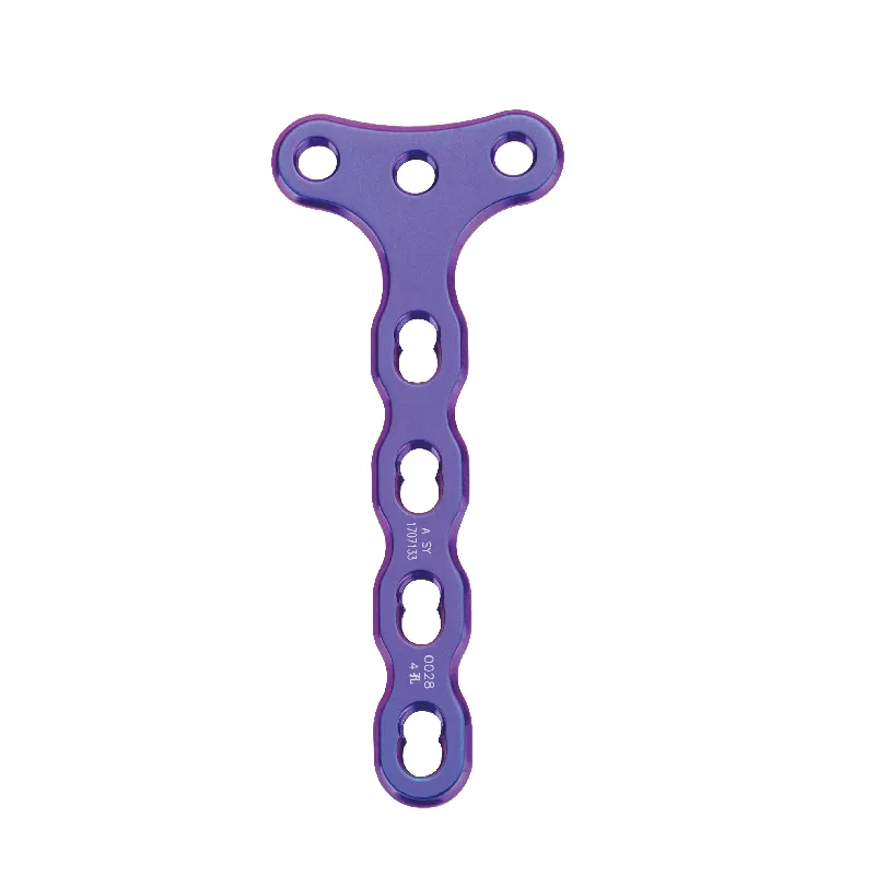
- T-plate configurations show 0.84 mm displacement versus 1.94 mm in π-plates
- Variable-angle locking mechanisms improve load sharing across trabecular bone
These insights empower surgeons to select plates aligned with specific fracture patterns—and help manufacturers prioritize clinically robust configurations before physical testing.
Optimizing Stiffness Matching to Prevent Stress Shielding or Nonunion
Balancing implant rigidity with biological requirements prevents two key complications:
- Stress shielding avoidance: Overly stiff plates cause bone resorption. FEA-guided stiffness reduction maintains 5–15% strain in fracture gaps—optimal range for callus formation.
- Micromotion control: Controlled 0.2–1 mm interfragmentary motion promotes healing; exceeding 2 mm significantly increases nonunion risk. Patient-specific FEA adjusts screw positioning to maintain this therapeutic window.
Strategic material assignment in cortical versus trabecular regions achieves strain compatibility, reducing nonunion rates by 22% in validated models.
Validation and Regulatory Alignment in Volar Locking Plate FEA
Bench Testing Correlation and ISO 14243-1—Compliant Boundary Conditions
To validate FEA simulations for volar locking plates, they need to match up closely with actual bench tests done under standard conditions. The ISO 14243-1 guidelines set the bar here, basically simulating how wrists actually work when loaded and constrained during normal activities. Research indicates that when FEA models hit over 90% agreement with mechanical testing results, doctors can trust them to predict things like tiny movements at the bone-implant interface and where stresses build up. Both the FDA's 21 CFR 820 regulations and EMA's Annex 11 requirements insist on this kind of validation link between computer models and real world mechanics. Manufacturers must document proof that their virtual prototypes behave similarly to actual implants in clinical settings. When this connection isn't there, the whole FEA process starts producing unclear results which slows down approval processes and puts patients at risk, especially those recovering from fractures in the lower part of the radius bone.
Frequently Asked Questions (FAQ)
What is Finite Element Analysis (FEA)?
Finite Element Analysis is a computerized method used by engineers to predict how products react to real-world forces, vibration, heat, fluid flow, and other physical effects, which is crucial in optimizing volar locking plate designs.
Why is FEA important for volar locking plate design?
FEA is important because it helps simulate biomechanical behaviors, test various designs, optimize screw arrangements, and evaluate stress distribution, thus reducing implant failure and revision surgeries.
What are the advantages of using patient-specific FEA models?
Patient-specific FEA models allow personalized designs that account for individual anatomical differences, improving load distribution and enhancing healing outcomes.
How does FEA contribute to regulatory compliance?
FEA assists in regulatory compliance by providing a validated virtual prototype that aligns with ISO 14243-1 standards, ensuring reliable predictions of biomechanical performance, thereby expediting regulatory approval processes.
Table of Contents
- Why Finite Element Analysis Is Essential for Volar Locking Plate Design
- Building an Anatomically Accurate FEA Model for Volar Locking Plate Simulation
- Biomechanical Evaluation: Stress, Strain, and Micromotion in Volar Locking Plate Design
- Validation and Regulatory Alignment in Volar Locking Plate FEA
- Frequently Asked Questions (FAQ)